Hydraulic Nut Size Chart Tapered Bore Bearings Wholesale Supplier
Select the correct Hydraulic Nut Size Chart for Tapered Bore Bearings to prevent inner ring slippage and shaft damage from mismatched piston stroke or thread pitch. Match exact specifications including 1:12 or 1:30 taper ratios to ensure sufficient axial displacement and reliable locking force in heavy-duty industrial applications.
 Written by
author
- Published on
- 8 min read
- Updated
Hydraulic Nut Size Chart Tapered Bore Bearings Wholesale Supplier
Bigger is not better. Selecting a hydraulic nut with excessive piston stroke or mismatched thread pitch does not guarantee superior locking force; it often leads to shaft damage and catastrophic bearing failure.
Correctly sizing a hydraulic nut for tapered bore bearings requires exact matching of the thread specification, piston stroke capacity, and the specific bearing taper ratio (typically 1:12 or 1:30) to ensure sufficient axial displacement without over-stressing the shaft. This precise alignment prevents inner ring slippage, overheating, and premature fatigue in heavy-duty applications.
I still remember the silence in the workshop after the conveyor line at a South African mining site shut down. It wasn’t the usual mechanical grind that stopped production; it was the smell of burnt metal. The maintenance team had installed spherical roller bearings with tapered bores but paired them with a generic hydraulic nut they found in the local supply cabinet. They didn’t check the Hydraulic Nut Size Chart for Tapered Bore Bearings. The piston stroke was too short for the required axial displacement on that specific shaft taper. The inner ring never fully seated. Under load, it slipped, generated intense heat, and seized the shaft. That incident taught me that the nut is not just an accessory; it is a critical precision component. [NEED_CITE: common causes of tapered bearing installation failures]
When distributors or MRO managers ask for a quote, I don’t just send a price list. I send the dimensional data. The difference between a smooth commissioning and a mid-six-figure loss often lies in millimeters of thread engagement and microns of clearance. Understanding how to read and apply these charts is essential for anyone responsible for industrial reliability.
Why Do Standard Size Charts Fail for Tapered Bores?
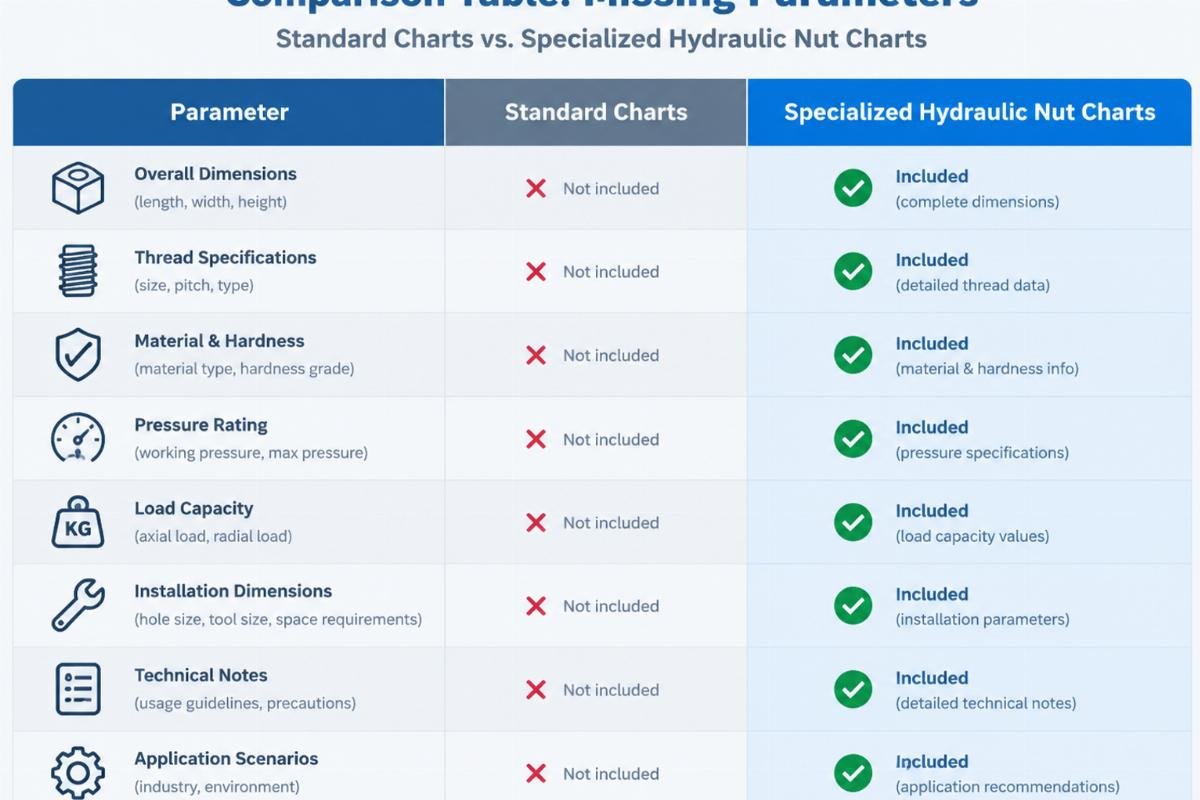
Standard metric or imperial thread charts are insufficient for tapered bore applications because they ignore the geometric relationship between the nut and the bearing’s internal taper. A standard chart might tell you that an M100x2 thread exists, but it won’t tell you if that thread pitch aligns with the hydraulic seal requirements of a specific bearing manufacturer’s design.
Tapered bore bearings rely on being driven up a tapered shaft seat to create an interference fit. The hydraulic nut must push the inner ring axially while simultaneously expanding it radially. If the thread pitch is incorrect, the mechanical advantage changes, leading to either insufficient preload or excessive torque that strips threads. [NEED_CITE: ISO standards for hydraulic mounting of bearings]
Consider a vibrating screen application in a quarry. The operator used a hydraulic nut with a coarse thread pitch instead of the fine pitch specified by the bearing manufacturer. During high-speed mounting, the cross-threading was not immediately visible. However, the uneven load distribution caused the hydraulic seal to fail before full pressure was reached. The result was inadequate locking force. When the screen started vibrating, the nut loosened, and the bearing walked off the shaft.
| Feature | Standard Thread Chart | Bearing-Specific Hydraulic Nut Chart |
|---|---|---|
| Thread Pitch Focus | General compatibility | Precise match to bearing lock nut design |
| Taper Ratio Consideration | Ignored | Critical (1:12, 1:30, etc.) |
| Piston Stroke Data | Not included | Essential for axial displacement calculation |
| Seal Integrity | Generic assumption | Verified for specific hydraulic pressure ranges |
| Risk Level | High for tapered bores | Low when matched correctly |
This comparison highlights why a generic approach fails. The Hydraulic Nut Size Chart for Tapered Bore Bearings must include piston stroke data, which is absent from standard fastener tables. Without this, you are guessing at the axial movement capability. [NEED_CITE: technical manuals for hydraulic mounting tools]
For buyers sourcing mixed-brand packages, this discrepancy is a major pitfall. SKF, FAG, NSK, and TIMKEN may use different thread profiles for similar bearing sizes. Assuming interchangeability based on outer diameter alone is a recipe for disaster. Verifying the specific thread pitch and diameter against the bearing’s lock nut specification is the first step in preventing installation errors.
How to Match Piston Stroke with Bearing Taper?
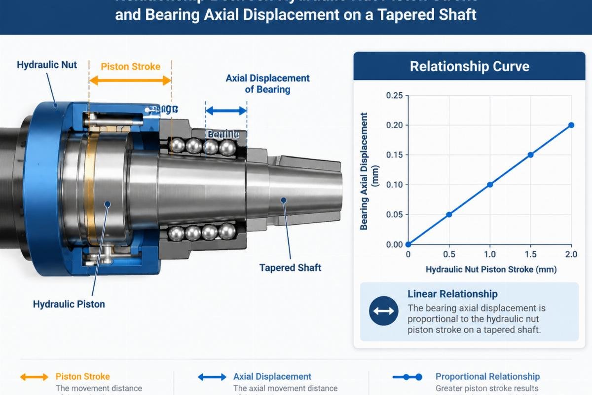
The piston stroke is the maximum distance the hydraulic nut can push the bearing inner ring axially. This distance must align perfectly with the shaft taper to achieve the correct preload. If the stroke is too short, the bearing will not reach its designated seating position. If it is too long, there is a risk of bottoming out against the shaft shoulder or damaging the nut’s internal seals.
The axial displacement required is calculated based on the taper ratio. For a standard 1:12 taper, a small axial movement results in a significant radial expansion. The formula involves the difference in diameter measurements before and after mounting. [NEED_CITE: axial displacement calculation methods for tapered bearings]
In a cement plant crusher application, the maintenance team ignored the taper ratio. They selected a hydraulic nut based solely on the shaft diameter. The piston stroke was adequate for a cylindrical bore but insufficient for the tapered seat. The inner ring did not expand enough to grip the shaft firmly. Under the heavy shock loads of crushing stone, the inner ring slipped relative to the shaft. This slippage caused fretting corrosion and eventual shaft scoring. The repair cost was several times the savings from using the wrong nut.
To avoid this, calculate the required axial displacement using the bearing manufacturer’s guidelines. Then, select a hydraulic nut whose piston stroke exceeds this value by a safe margin, typically ten to twenty percent, to account for seal compression and mechanical play. [NEED_CITE: manufacturer recommendations for hydraulic nut selection]

When reviewing a Hydraulic Nut Size Chart for Tapered Bore Bearings, look for the “Max Stroke” column. Compare this value with your calculated axial displacement. If the chart does not provide stroke data, request it from the supplier. Never assume. In my experience, the most reliable suppliers provide complete traceability documents that include these critical dimensional specs.
What Are the Critical Thread Specifications to Verify?
Thread specifications are the interface between the hydraulic force and the bearing. The two most critical parameters are the thread diameter and the thread pitch. A mismatch here can cause cross-threading, galling, or seal failure.
Many tapered bore shafts use specific thread forms that differ from standard ISO metric threads. For example, some manufacturers use a trapezoidal thread profile for higher load capacity and easier cleaning in dirty environments. Using a standard metric nut on a trapezoidal thread will destroy both components. [NEED_CITE: thread form standards for industrial locking devices]
A European wind farm operator once faced repeated failures in their gearbox main bearings. The issue was traced back to the hydraulic nuts used during maintenance. The nuts had the correct diameter but the wrong pitch. During tightening, the threads engaged partially, creating a false sense of security. Under operational torque, the threads stripped, and the bearing lost its preload. The resulting vibration damaged the gearbox housing, leading to a prolonged downtime.
| Specification | Risk of Mismatch | Verification Method |
|---|---|---|
| Thread Diameter | Nut will not fit or will be loose | Caliper measurement against bearing lock nut |
| Thread Pitch | Cross-threading, stripping, seal damage | Thread gauge or pitch measurement tool |
| Thread Form | Poor load distribution, galling | Visual inspection and manufacturer datasheet |
| Seal Interface | Hydraulic oil leakage, pressure loss | Check seal material compatibility and dimensions |
Verifying these specs requires more than a visual check. Use thread gauges to confirm the pitch. Check the bearing manual for the specific thread form required. If the Hydraulic Nut Size Chart for Tapered Bore Bearings lists multiple thread options for a single size, ensure you select the one that matches the bearing’s lock nut exactly. [NEED_CITE: best practices for thread verification in maintenance]
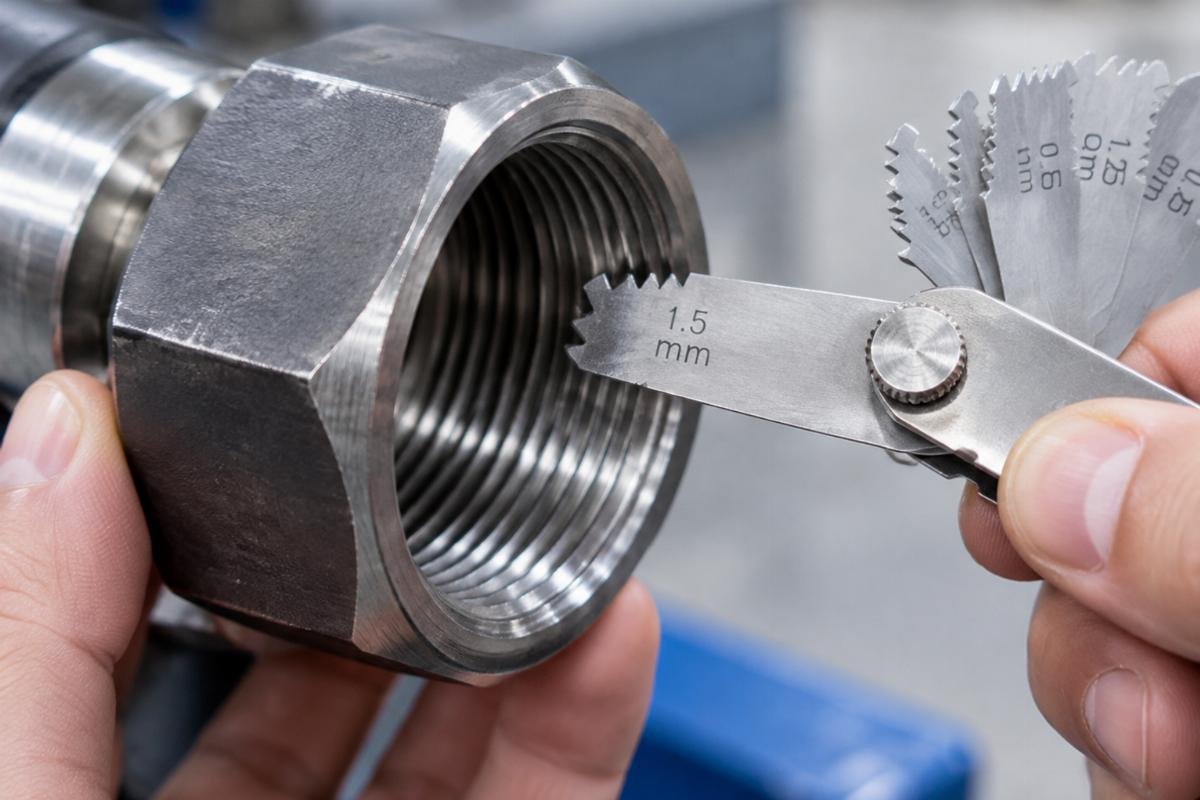
For distributors stocking multi-brand inventory, this means maintaining separate SKUs for nuts that look identical but have different thread pitches. Labeling clearly and providing technical datasheets to end-users can prevent these costly mix-ups.
How to Validate Your Hydraulic Nut Selection Before Installation?
Validation is the final safeguard against installation errors. It involves cross-referencing dimensional tables and calculating the required oil pressure. This step ensures that the selected nut can generate the necessary locking force without exceeding the yield strength of the shaft or the nut itself.
Start by confirming the bearing’s required mounting pressure. This value is derived from the desired interference fit and the friction coefficient between the shaft and bearing. Then, check the hydraulic nut’s effective area to determine the oil pressure needed to generate the corresponding axial force. [NEED_CITE: hydraulic pressure calculation for bearing mounting]
In a steel mill rolling stand, engineers validated their selection by performing a dry run. They measured the initial position of the bearing, applied low pressure to seat the nut, and then gradually increased pressure while monitoring axial displacement. They compared the actual displacement with the theoretical value from the Hydraulic Nut Size Chart for Tapered Bore Bearings. The match confirmed that the nut was correctly sized. This proactive validation prevented a potential failure that could have halted the entire production line.
Key validation steps include:
- Measure the initial axial position of the bearing inner ring.
- Calculate the target axial displacement based on the taper ratio and required interference.
- Verify the hydraulic nut’s piston stroke exceeds the target displacement.
- Confirm the thread pitch and diameter match the bearing lock nut.
- Check the hydraulic seal integrity and pressure rating.
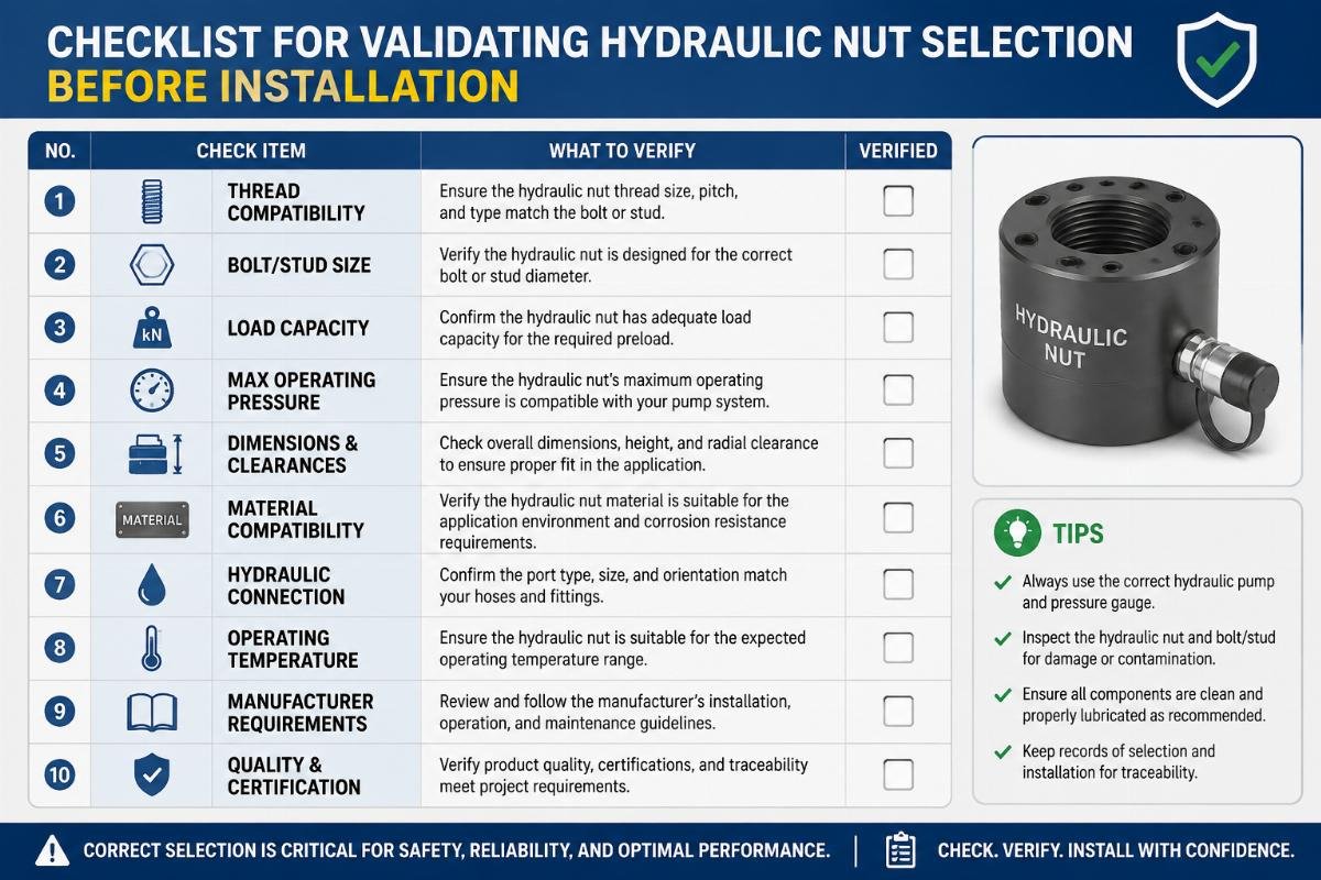
By following these steps, you ensure that the hydraulic nut is not just a compatible part, but the right part for the job. This level of diligence is what separates professional maintenance operations from those prone to recurrent failures. For complex projects involving mixed brands, having access to technical selection support and complete traceability docs is invaluable. It allows for confident decision-making even when dealing with non-standard or legacy equipment.
Conclusion
Precision in sizing prevents catastrophe. Matching the hydraulic nut to the bearing’s specific thread, stroke, and taper requirements is non-negotiable for reliable industrial operation.
Ignoring these details leads to inner ring slippage, shaft damage, and unplanned downtime. Always verify specifications against the manufacturer’s data and use a comprehensive Hydraulic Nut Size Chart for Tapered Bore Bearings to guide your selection. Proper validation ensures that every installation contributes to long-term equipment health rather than becoming a future failure point.
Tags

About the author
author
Editor covering global sourcing, supplier verification, and industrial product knowledge. Content is compiled from manufacturer specifications, industry standards, and hands-on experience with international B2B buyers. Every article is fact-checked before publishing to help procurement professionals make informed decisions.
More articles by author